Table Of Content
ERD diagrams are commonly used in conjunction with a data flow diagram to display the contents of a data store. They help us to visualize how data is connected in a general way, and are particularly useful for constructing a relational database. An attribute that can be derived from other attributes of the entity type is known as a derived attribute. In ER diagram, the derived attribute is represented by a dashed oval. An attribute composed of many other attributes is called a composite attribute.
Construct Conceptual, Logical and Physical ER Model
An ER diagram is used to visualize the relationships between entities in a database. This is useful for engineers hoping to either document a database as it exists for troubleshooting or to sketch out a design of a new database. As we know, a database is a collection of where all data of a system are stored. Surely, you will find lots of information in a database which is why it can be a bit difficult for one to analyze the elements at a glance. Entity-relationship diagrams or ERDs provide a visual way to understand the relationship between entities, which in other words, a container of information.
Try SmartDraw's Entity Relationship Diagram Software Free
By using its drag-and-drop feature, working with diagrams is a lot easier. You can also create ER diagrams from scratch or generate ERD automatically from your DBMS to upload the database tables. And what makes this a recommended ER diagram creator is that it enables users to export your ERD to database services such as MySQL, Oracle, SQL Server, and so on. This is a web-based tool that allows you to create entity relationship diagrams without registration required.
Entity Relationship Model
You need to study the files, forms, reports, data currently maintained by the organization to identify attributes. You can also conduct interviews with various stakeholders to identify entities. Initially, it’s important to identify the attributes without mapping them to a particular entity. ER Modeling helps you to analyze data requirements systematically to produce a well-designed database. So, it is considered a best practice to complete ER modeling before implementing your database. At first look, an ER diagram looks very similar to the flowchart.

ER Diagrams contain different symbols that use rectangles to represent entities, ovals to define attributes and diamond shapes to represent relationships. Creately is a great option if you are looking for an ER diagram tool that lets you do more than just one type of diagram. The tool provides a lot of editing options which are useful for creating various charts and diagrams.
How to make an ER diagram online in Lucidchart
Since a physical ER Diagram provides a blueprint of an actual database, the entities in such an ERD are aligned with datastores in a DFD. While all the three levels of an ER model contain entities with attributes and relationships, they differ in the purposes they are created for and the audiences they are meant to target. An attribute has a name that describes the property and a type that describes the kind of attribute it is, such as varchar for a string, and int for integer. When an ERD is drawn for physical database development, it is important to ensure the use of types that are supported by the target RDBMS.
ER Yacht Design reveals 90m explorer yacht ER90 - Boat International
ER Yacht Design reveals 90m explorer yacht ER90.
Posted: Wed, 20 Mar 2024 07:00:00 GMT [source]
The number of different entity sets participating in a relationship set is called the degree of a relationship set. An attribute consisting of more than one value for a given entity. For example, Phone_No (can be more than one for a given student).
Gensler’s Mexico City Office: A Model for the Future Workplace
Also known as PK, a primary key is a special kind of entity attribute that uniquely defines a record in a database table. In other words, there must not be two (or more) records that share the same value for the primary key attribute. The ERD example below shows an entity 'Product' with a primary key attribute 'ID', and a preview of table records in the database. The third record is invalid because the value of ID 'PDT-0002' is already used by another record. Total Participation – Each entity in the entity set must participate in the relationship.
Conceptual, logical and physical data models
With it, you can access hundreds of templates including ERDs allowing you to instantly create a structure of your database. In addition, you can create as many diagrams are required without even bothering about expiration. On top of that, exporting diagrams to images with no watermark could be done through this ER diagram maker. This is generally the first step in thinking about a systems data design.
You can export your database structure as a CSV file (there are some scripts on how to this here), then have a program generate the ERD automatically. You're either designing a new schema or you need to document your existing structure. The traditional Chen ERD is like a flowchart with connected symbols for entities, relationships, and attributes. Since its first introduction by Chen in the 70s, others have proposed different cardinality notations, but the basic symbols used and how they're connected tend to look the same.
In ER diagram, a multivalued attribute is represented by a double oval. A Strong Entity is a type of entity that has a key Attribute. Strong Entity does not depend on other Entity in the Schema. It has a primary key, that helps in identifying it uniquely, and it is represented by a rectangle. An entity can be place, person, object, event or a concept, which stores data in the database. The characteristics of entities are must have an attribute, and a unique key.
Are you planning a home remodeling project in your San Diego home? Or are you in the beginning stages of finally planning your big, beautiful, custom home design? Whatever your project ideas, wouldn’t it be great if you could see your finished home before you spend all that time and money on an architect or contractor?
You can collaborate with business analysts and engineers to get feedback and comments on both conceptual and logical ER diagrams as well as physical database schemas. A weak entity is a type of entity which doesn’t have its key attribute. It can be identified uniquely by considering the primary key of another entity. ER Model stands for Entity Relationship Model is a high-level conceptual data model diagram.
This is an online mindmapping and ER diagram tool that you can use for free. What makes this tool so great, is the extensive amount of shapes and elements it provides in its library. These shapes are useful when making all kinds of diagrams like ER diagrams.
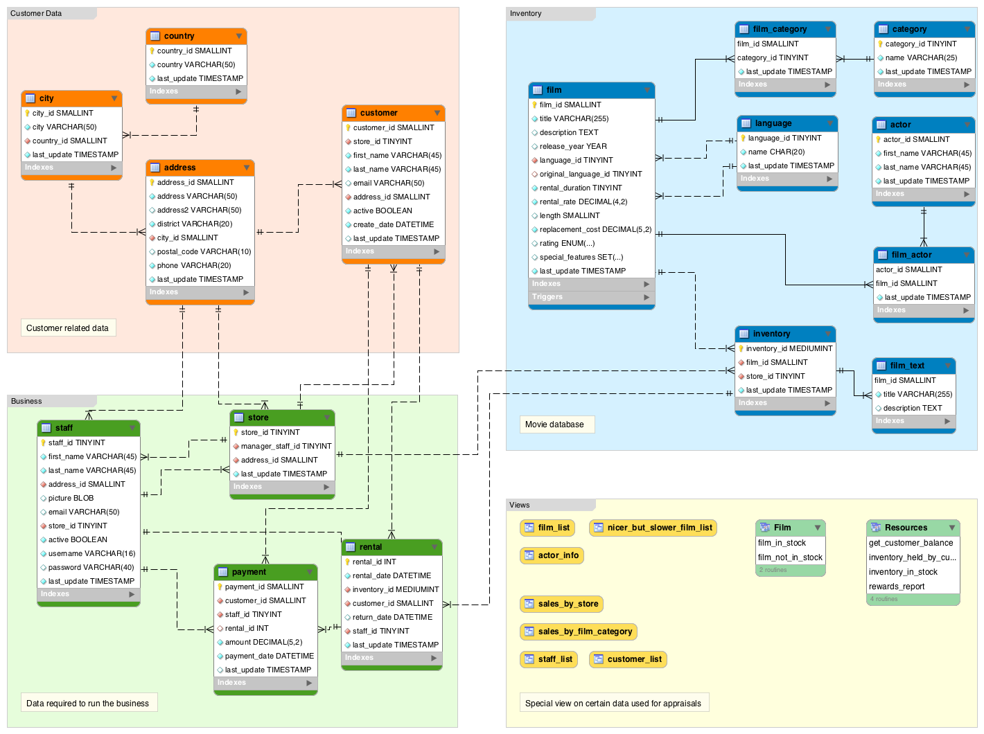
Below you can see an example of a diagram showing entities, their attributes, and the relationships between entities. Designing an ERD involves a methodical process that starts with identifying the entities in the system and their attributes as well as the relationships between entities. Let's go a bit deeper into the concept of entities, attributes, and relationships. The tool is dedicated to creating ER diagrams which means that all options and elements in it serves only one purpose. As an ER diagram tool, we can say that ERDPlus is a decent one because it is free. Add that to the fact that it is really easy to use, compared with other tools that have confusing interface.
Access standard shapes, build from templates, and import database tables and schemas to customize your ER diagram to your needs. Some ER diagram tools might also offer functionality like data input and export, database reverse engineering, and real-time collaboration with other users. Second, ER diagrams are readily translatable into relational tables which can be used to quickly build databases. In addition, ER diagrams can directly be used by database developers as the blueprint for implementing data in specific software applications. ER diagrams can get really complicated, especially in big systems with lots of entities and relationships.

No comments:
Post a Comment