Table Of Content

In those that do, however, attributes are represented by oval shapes. As database systems became more complex, ER diagrams remained important tools for designing and managing databases. They helped developers and users understand how data was organized and connected. When documenting a system or process, looking at the system in multiple ways increases the understanding of that system.
What is ER Diagram?
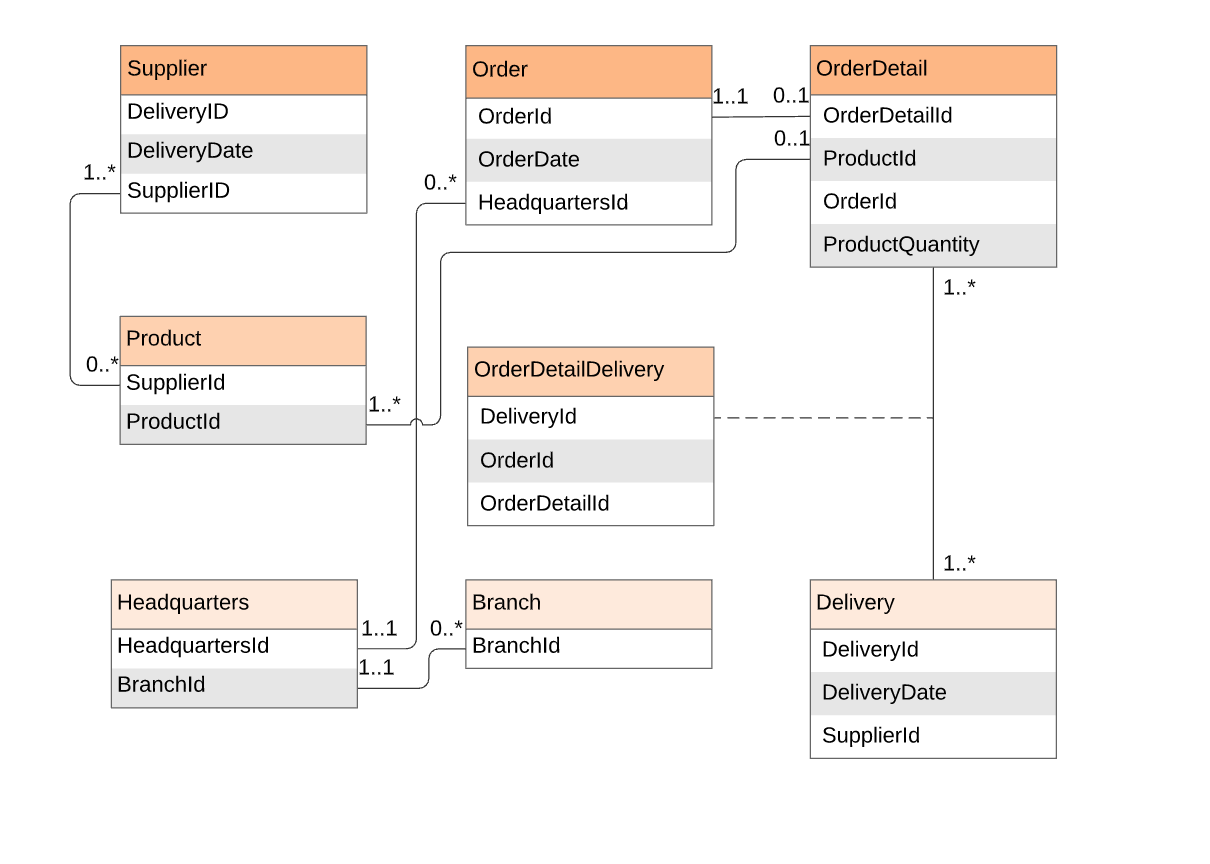
Below you can see an example of a diagram showing entities, their attributes, and the relationships between entities. Designing an ERD involves a methodical process that starts with identifying the entities in the system and their attributes as well as the relationships between entities. Let's go a bit deeper into the concept of entities, attributes, and relationships. The tool is dedicated to creating ER diagrams which means that all options and elements in it serves only one purpose. As an ER diagram tool, we can say that ERDPlus is a decent one because it is free. Add that to the fact that it is really easy to use, compared with other tools that have confusing interface.
What is an ER diagram (ERD)?
However, ER Diagram includes many specialized symbols, and its meanings make this model unique. The purpose of ER Diagram is to represent the entity framework infrastructure. Many platforms and tools offer competitive features at affordable prices. Online platforms are more feasible for modern software projects, as they more readily adapt to remote and distributed teams. Lucidchart is a multi-purpose online solution that supports many types of diagrams, including ER diagrams.
Conceptual, Logical and Physical data models
Data modeling is one of the most critical parts of a software project. Database architects use ER diagrams (also called ERDs or Entity Relationship Diagrams) as a data modeling technique. While it's possible to sketch an ERD diagram using general-purpose drawing tools, using a dedicated ER diagram tool can provide a much smoother and more efficient experience. Such tools have specialized features that can assist in the database design process, making it quicker and more accurate. Unlike the above solutions, this tool produces diagrams by writing codes. In other words, this is favorable for users who enjoy editing using your keyboard.
Try SmartDraw's ER Diagram Tool Free
Since a physical ER Diagram provides a blueprint of an actual database, the entities in such an ERD are aligned with datastores in a DFD. While all the three levels of an ER model contain entities with attributes and relationships, they differ in the purposes they are created for and the audiences they are meant to target. An attribute has a name that describes the property and a type that describes the kind of attribute it is, such as varchar for a string, and int for integer. When an ERD is drawn for physical database development, it is important to ensure the use of types that are supported by the target RDBMS.
Visual Paradigm supports reverse engineering to import your database from DDL (Data Definition Language) and forward engineering to create the DDL or database from your ERD. Automatic foreign key generation when you create an ERD is a nice touch. Let’s compare the features of a few top-rated ER diagram online tools and see how they support database design.
Automatic foreign key generation
What is an entity relationship diagram (ERD)? Definition from TechTarget - TechTarget
What is an entity relationship diagram (ERD)? Definition from TechTarget.
Posted: Mon, 28 Feb 2022 22:03:07 GMT [source]
The ER data model specifies enterprise schema that represents the overall logical structure of a database graphically. It may contain entities with attribute sharing similar values. Entities are represented by their properties, which also called attributes. For example, a student entity may have a name, age, class, as attributes.
As a matter of fact, making an ERD is really simple using this tool since all you need is to drag and drop the elements and arrange them according to your purpose. It also supports online collaboration which lets multiple users work on a single diagram simultaneously. This tool is an ER diagramming tool that works on popular web browsers allowing you to create diagrams anytime, anywhere. One of the highlights of this program is it provides version history allowing you to compare your revisions and identify discrepancies like nullability, data type, and defaults. Besides, this ER diagram tool grants access to dark and light themes as well as viewing modes that suit different purposes like presentation.
Rethinking the E.R.: Hospital Emergency Department Plans - ARCHITECT Magazine
Rethinking the E.R.: Hospital Emergency Department Plans.
Posted: Fri, 08 Oct 2021 16:21:09 GMT [source]
Adult-Appropriate Loft Beds You Can Buy Online
In a Business Process Diagram, there is a symbol called Data Object, which represents the data input into / output from process activities. Also known as FK, a foreign key is a reference to a primary key in a table. It is used to identify the relationships between entities.
The table below shows the difference between the three data models. The entity relationship diagram is a high-level conceptual data modeling diagram. It helps with systematically analyzing and identifying data requirements needed for effective database designing. An Entity Relationship (ER) Diagram is a type of flowchart that illustrates how “entities” such as people, objects or concepts relate to each other within a system. ER Diagrams are most often used to design or debug relational databases in the fields of software engineering, business information systems, education and research.
In this example, student S1 is enrolled in C1 and C3 and Course C3 is enrolled by S1, S3, and S4. Once, you have a list of Attributes, you need to map them to the identified entities. Ensure an attribute is to be paired with exactly one entity.
Thus, we’ve put together a list of free ER diagram tools that will help you construct a relational and logical structure of a database. ER diagrams are visual tools that are helpful to represent the ER model. Peter Chen proposed ER Diagram in 1971 to create a uniform convention that can be used for relational databases and networks. He aimed to use an ER model as a conceptual modeling approach.
With it, you can access hundreds of templates including ERDs allowing you to instantly create a structure of your database. In addition, you can create as many diagrams are required without even bothering about expiration. On top of that, exporting diagrams to images with no watermark could be done through this ER diagram maker. This is generally the first step in thinking about a systems data design.
Besides collaboration and tracking changes, this ER diagram maker enables you to import images and as well as export diagrams. Unlike other ER diagram tools, we eliminate the hassle of managing Salesforce object infrastructure and let you visualize hypothetical changes before implementing them in Salesforce. As databases change over time, ER diagrams might need to be updated to show the changes accurately. Keeping track of these changes and making sure the diagrams match the actual database can take a lot of time and effort.
The sample records help readers understand the format of data that will be inserted. Besides, the records will be output in data specification. You can also insert them into database upon database generation. Relationships describe how entities interact with each other. These interactions are usually representations of verbs or actions in the real world.


No comments:
Post a Comment